Generate an enclosure
Requires FreeCAD 0.20 or newer. Open the Enclosure tab.
Two ways in
Section titled “Two ways in”From a board file — pick a .kicad_pcb. No live KiCad connection needed. The
app uses kicad-cli’s own DXF and drill export to read the real outline and
mounting-hole positions.
From a live board — if KiCad is open with a board loaded, read it directly over the API.
Either way, the geometry comes from your actual board. You are not retyping coordinates.
What you get
Section titled “What you get”A hollow body sized to your board with clearance, standoff cylinders at your real mounting-hole positions, a solid floor and an open top — the standard 3D-printable tray — plus an optional lid you can toggle independently.
Adjustable: wall thickness, clearance around the board, standoff height. Change a value and regenerate against the same board; you are not starting over each time.
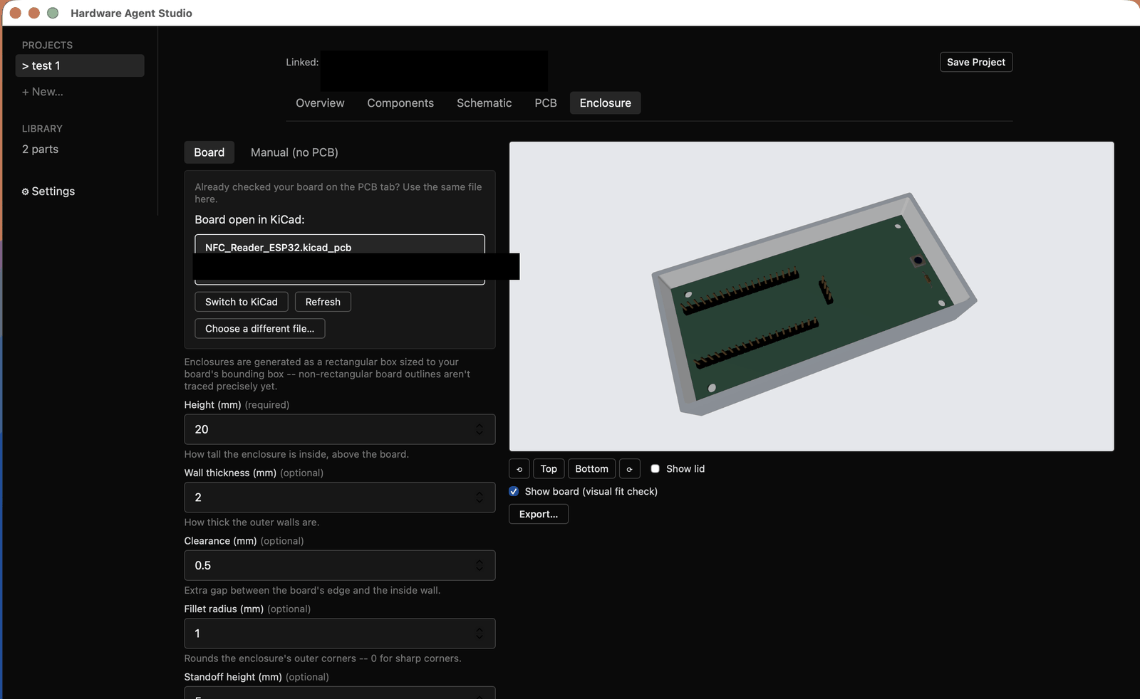
Preview it in the 3D viewer with free orbit or camera presets, then export STEP for CAD or GLB for a mesh viewer.
Mounting holes
Section titled “Mounting holes”Only holes the app recognises as mounting holes get standoffs. An unrecognised hole is excluded from the geometry but still reported, so you can see it was found and decide. A build does not fail because one hole was unfamiliar.
If your board has no mounting holes, you get a box with no standoffs. The app does not invent hole positions.
What it does not do yet
Section titled “What it does not do yet”All real, all wanted, none built:
- Cutouts for connectors — USB, headers, anything that needs to reach the outside
- Fastener or latch suggestions for holding the lid on
- Noticing your board is missing mounting holes and suggesting where they could go
- Shapes that follow a non-rectangular board outline in full detail
Treat the output as a starting body you refine in FreeCAD, not a finished case. That is what it is designed to be.